

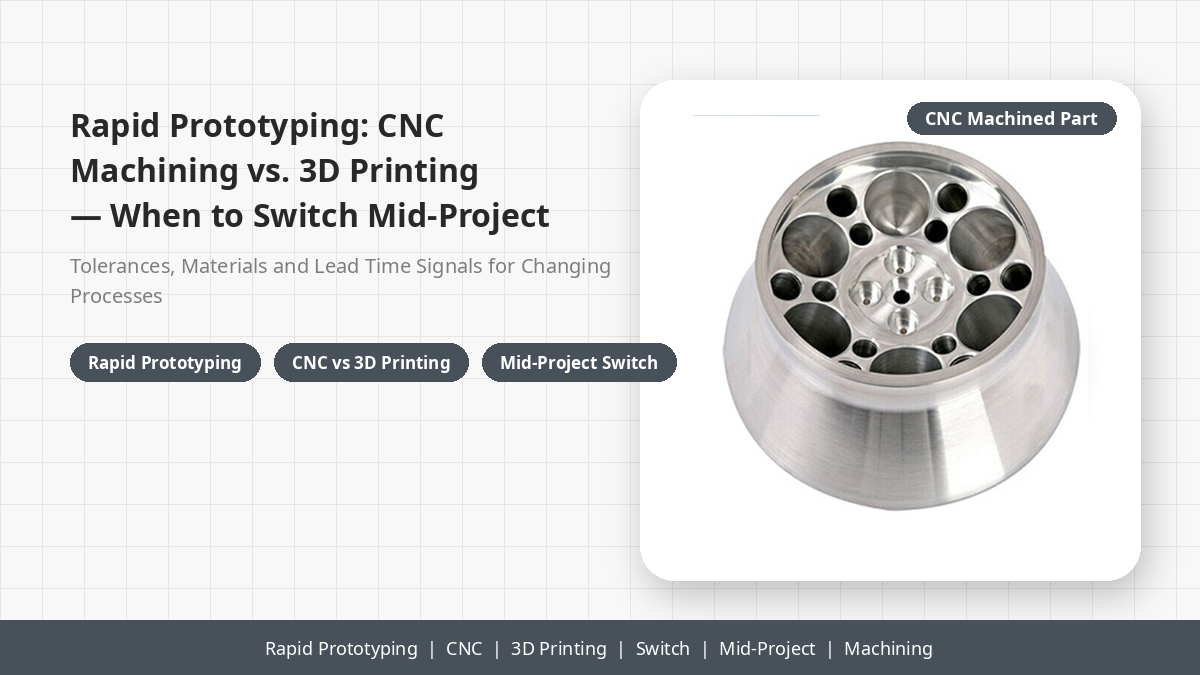


Rapid Prototyping: CNC Machining vs. 3D Printing — When to Switch Mid-Project
The right rapid-prototyping process at the start of a project is almost never the right process at the end. 3D printing is the right answer when the engineer needs the part on the desk in days; CNC machining is the right answer when the project needs the production material, the production tolerance, and the production surface finish. The mistake most product-development teams make is locking one process for the whole project — which produces a prototype that validates the wrong thing at the wrong checkpoint, or costs more than it should at the checkpoint where the team needed iteration speed.
Quick Summary
- Four project checkpoints: concept validation, fit-and-function, pre-production, low-volume production — each has a different optimal process, and the right program switches mid-project rather than locking one process for the whole project.
- 3D printing wins at checkpoint 1 — days not weeks for lead time, with a material that approximates the production material's mechanical properties.
- CNC machining wins at checkpoint 3 — the production material, the production tolerance, and the production surface finish the project needs to validate the supplier's process.
- The mid-project switch happens at the checkpoint 2 to checkpoint 3 transition — triggered by the material change that the project needs to validate, paid for in CNC programming and fixturing time.
- The right program mixes the two processes within a complex product — 3D printing for the parts that need fast iteration and complex internal features; CNC machining for the parts that need production material and tight tolerance.
For a product development engineer, mechanical engineer, or hardware startup founder running a rapid-prototyping program, the right framework is the framework that walks through the four checkpoints and the right process at each. The FRIMA custom service page is the catalog starting point; the CNC milling parts category is the right reference for the production-material prototypes that the project needs at the later stages.
What Are the Four Project Checkpoints?
A rapid prototyping project moves through four checkpoints, each with a different goal and a different optimal process.
- Checkpoint 1 — Concept Validation. The project is testing the design concept against the functional requirement. The part has to be on the engineer's desk in days. The right process is 3D printing — SLA, MJF, or FDM — with a material that approximates the production material's mechanical properties.
- Checkpoint 2 — Fit-and-Function. The project is testing the part against the assembly — the mating geometry, the tolerance stack-up, the functional performance. The right process depends on the material and the tolerance.
- Checkpoint 3 — Pre-Production. The project is testing the part against the production process — the supplier's tooling, the production material, the surface finish, the cycle time. The right process is CNC machining because the project needs the production material, the production tolerance, and the production surface finish to validate the supplier's process.
- Checkpoint 4 — Low-Volume Production. The project has validated the design and is shipping the first low-volume production run. The right process depends on the volume and the material.
The single most under-appreciated variable in real rapid-prototyping programs: the assumption that one process fits all four checkpoints. It does not. A product development team that runs CNC machining at checkpoint 1 loses days to fixturing and programming for a part that is about to be redesigned. A team that runs 3D printing at checkpoint 3 loses the validation the supplier needs to commit to production.
When to Choose 3D Printing
3D printing is the right answer when the project needs iteration speed over production precision. SLA and MJF processes can deliver a part in 1 to 3 working days from CAD acceptance, with the long end on large parts that require long print times. The materials available — photopolymer resins, nylon powder, thermoplastic filaments — approximate the production material's mechanical properties but do not match them.
The right conversation is the conversation that picks 3D printing at the right checkpoint. Checkpoint 1 (concept validation) is the strongest case. Checkpoint 2 (fit-and-function) for plastic or low-temperature applications is a strong case. Checkpoint 3 (pre-production) and checkpoint 4 (low-volume production) are weak cases for 3D printing, because the project at those stages needs the production validation that only CNC machining or injection molding can provide.
When to Choose CNC Machining
CNC machining is the right answer when the project needs the production material, the production tolerance, and the production surface finish. CNC machining prototypes a wide range of production metals — aluminum (6061, 7075), steel (1018, 4140, A2, D2), stainless (303, 304, 316), brass, copper, and titanium — and engineering plastics (Delrin, PEEK, UHMW, polycarbonate, nylon). The right material is the production material, because the CNC prototype's mechanical and thermal properties match the production part's properties, which is what makes the prototype validation reliable.
The right conversation is the conversation that picks CNC machining at the right checkpoint. Checkpoint 3 (pre-production) is the strongest case. Checkpoint 4 (low-volume production) for metal parts below roughly 50 to 100 units is a strong case. Checkpoint 2 (fit-and-function) for metal applications with tight tolerance is a strong case. Checkpoint 1 (concept validation) is a weak case for CNC machining, because the iteration speed 3D printing delivers is what the project needs at this stage.
| Checkpoint | Project Goal | Right Process | Lead Time |
|---|---|---|---|
| 1. Concept Validation | Test the design concept against the functional requirement | 3D printing (SLA / MJF / FDM) | 1–3 working days |
| 2. Fit-and-Function | Test the part against the assembly | 3D printing (plastic) or CNC machining (metal, tight tolerance) | 1–10 working days |
| 3. Pre-Production | Test the part against the production process | CNC machining (production material and tolerance) | 3–10 working days |
| 4. Low-Volume Production | Ship the first low-volume production run | CNC machining (metal below 100 units) or injection molding (plastic above 500 units) | Volume-dependent |
How Does the Mid-Project Switch Work?
The mid-project switch from 3D printing to CNC machining happens at the checkpoint 2 to checkpoint 3 transition, when the project moves from fit-and-function validation to pre-production validation. The trigger for the switch is the material change — the 3D-printed plastic part cannot represent the production metal part's mechanical properties, thermal behavior, or surface finish.
The cost of the switch is the CNC programming and the fixturing time. A simple geometry can move from 3D-printed prototype to CNC-machined prototype in 3 to 5 working days; a complex multi-setup geometry can take 5 to 10 working days. The right program accounts for the switch time at the project calendar stage, because the switch time is the calendar gap the project runs against.
The right way to think about the mid-project switch: it is a deliberate checkpoint transition, not an emergency re-spec. The project that runs 3D printing through checkpoint 2 and CNC machining from checkpoint 3 is a project that has planned the switch from the start. The project that locks 3D printing at checkpoint 1 and then scrambles to switch at checkpoint 3 is the project that pays for the switch in production slip.
What Is the Right Way to Mix the Two Processes?
The mixed approach is the right answer for a complex product. 3D printing for the parts that need fast iteration and complex internal features (typically the enclosure, the cover, the internal bracket); CNC machining for the parts that need production material and tight tolerance (typically the structural frame, the shaft, the mounting plate, the load-bearing interface). The mixed approach is what most product development teams use in practice, and the right program scopes the mixed approach against the assembly fit-and-function checkpoint, not against a single process for the whole product.
The right supplier for the mixed approach is the supplier that runs both processes on the same engineering footprint. A project that runs 3D printing at one supplier and CNC machining at another supplier pays the coordination cost twice — once in the file-transfer handoff, once in the tolerance-stack-up risk. The right supplier runs both processes and sequences the prototype delivery against the assembly fit-and-function plan.
Honest caveat: a single-process prototyping program is not the right answer for every project. A buyer who is running a simple, single-material concept validation overpays for the CNC option. A buyer who is running a pre-production validation overpays for the 3D printing option. The right conversation is the conversation that picks the process at the right checkpoint rather than the conversation that picks one process for the whole project.
Frequently Asked Questions
When should I choose CNC machining over 3D printing for rapid prototyping?
Choose CNC machining when the project needs the production material (typically metal), the production tolerance (typically 0.05 mm or tighter), or the production surface finish (typically Ra 0.8 or smoother). Choose 3D printing when the project needs the part on the engineer's desk in days rather than weeks, when the material and tolerance can be approximated by a printable polymer, or when the geometry is too complex for a single-setup CNC operation.
Can I 3D print metal parts for prototyping?
Yes, through DMLS (direct metal laser sintering) and binder jetting processes. DMLS produces near-net-shape metal parts that approximate the production material's mechanical properties but require post-machining for tight-tolerance features. Binder jetting produces green parts that require sintering and infiltration, which adds process steps. The right metal 3D printing process depends on the part's geometry, the production material, and the tolerance the project requires.
What tolerances can a 3D-printed part hold?
SLA and MJF processes typically hold +/- 0.1 mm to +/- 0.2 mm on well-designed features, with the tighter tolerance achievable on smaller features and the looser tolerance on larger features that are more sensitive to warpage. CNC machining typically holds +/- 0.025 mm to +/- 0.05 mm on tight-tolerance features, with the broader tolerance on complex geometry that requires multiple setups. The right tolerance is the tolerance the project requires, not the tighter tolerance the process can deliver.
What materials can CNC machining prototype?
CNC machining prototypes a wide range of production metals — aluminum (6061, 7075), steel (1018, 4140, A2, D2), stainless (303, 304, 316), brass, copper, and titanium — and engineering plastics (Delrin, PEEK, UHMW, polycarbonate, nylon). The right material is the production material, because the CNC prototype's mechanical and thermal properties match the production part's properties, which is what makes the prototype validation reliable.
What materials can 3D printing prototype?
SLA uses photopolymer resins with mechanical properties from rigid ABS-like to flexible rubber-like. FDM uses thermoplastic filaments (PLA, ABS, PETG, nylon, polycarbonate, PEEK). MJF uses nylon powder with isotropic mechanical properties. SLS uses nylon, TPU, or polypropylene powder. Metal 3D printing uses aluminum, stainless steel, titanium, Inconel, and maraging steel powders. The right material is the material that approximates the production material's mechanical and thermal properties for the checkpoint the project is at.
How long does a CNC prototype take?
A CNC prototype typically takes 3 to 10 working days from CAD acceptance, with the long end on complex multi-setup geometries and the short end on simple geometries that fit a single setup. The right program accounts for the CAD-to-CAM programming time, the fixturing time, the machine time, and the post-machining inspection time, all of which the right supplier sequences in parallel where possible.
How long does a 3D-printed prototype take?
An SLA or MJF prototype typically takes 1 to 3 working days from CAD acceptance, with the long end on large parts that require long print times and the short end on small parts that print in hours. The right program accounts for the print time, the post-curing time, and the support-removal time, all of which the right supplier sequences in parallel where possible.
Can I mix CNC machining and 3D printing in the same project?
Yes, and the mixed approach is often the right answer for a complex product. 3D printing for the parts that need fast iteration and complex internal features, CNC machining for the parts that need production material, tight tolerance, and surface finish. The mixed approach is what most product development teams use in practice, and the right program scopes the mixed approach against the assembly fit-and-function checkpoint, not against a single process for the whole product.
How Does FRIMA Run the Program Against This Framework?
FRIMA produces the custom CNC machining service on a Ningbo manufacturing footprint, with 15+ years of custom machined parts, special drawing production, fabrication, and assembly mechanism experience. The custom service page covers the standard catalog range; the CNC milling parts category is the right reference for the production-material prototype tier; the contact page is where a product development engineer who is building or reviewing a rapid prototyping program starts the conversation.
The framework in this article is the framework FRIMA runs against every program — the right process at the right checkpoint, the right mid-project switch at the right transition, and the right mix within a complex product. The program that locks all three against the project checkpoint calendar is the program that delivers the prototype validation the engineering team needs.
Spec'ing a rapid prototyping program?
Send us the part geometry, the production material, the checkpoint the project is at, and the lead time. We will return a written process recommendation and a sample plan.